
Understanding Propagation Delay: A Brief Discussion on Its Relevance in PCB Designing
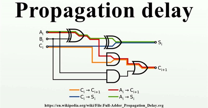
Finding out the propagation delay (tpd) on a circuit board requires an acute understanding of complex calculations, but in definition, the concept is quite straightforward. Propagation delay is quite simply the time necessary (aka the “delay”) for digital signals to travel between comparator inputs and outputs.
Why is Propagation Delay a Necessary Measurement?
In the absence of the exact measurements, it would be impossible to sync all the signals on a board, which would in turn, make way for a skew. Skews can be managed with differential pairing effectively, but given how complicated that can get, it’s best to avoid skews altogether by getting accurate propagation delay measurements beforehand.
How Should You Calculate Propagation Delay While Designing Your PCB?
Ideally, a propagation delay calculator should come with the PCB designer software itself, as it would be extremely time consuming, error-prone and archaic to try and calculate the propagation delay manually every time. Once you have the necessary readings, you will be able to set the compensations and synchronize all signals simultaneously.
What Parameters Affect Propagation Delay?
There are far too many factors that can potentially affect propagation delay to touch over them all here, but the following should introduce the most consistent factors nonetheless.
Overdrive
One of the most common, if not the most common factor which affects a board’s expected tpd, is the overdrive on its comparator. Which is also the reason why overdrive is a necessary unit to calculate first in order to calculate propagation delay with accuracy. Similar to the power supply unit’s voltage, the more powerful the overdrive is, the lower the delay would be.
Power Supply Voltage
There is, of course, a direct relationship between the voltage capacity of the power supply unit, and the overall time a signal takes to get from the input to the output. As you would expect, a power supply unit with more juice will deliver the signal faster to its source, thereby reducing the propagation delay as a result.
The real question is, can the output’s power supply voltage affect propagation delay when the input and output power supply are separated? The answer would be yes, it can affect the speed of the signal’s transfer from input to output in the same way.
Is There a Relationship Between Heat and Propagation Delay?
This is a gray area, because no established links can be confirmed between the two. However, the two are somewhat connected when high-speed frequencies are involved, albeit not in a way that can be measured with accuracy unfortunately.
The delay can prove to be bothersome if it’s above the expected ranges, which is one more reason why we need to measure it during various stages of the PCB’s design.
In such cases where the propagation delay is too high, differential pair routing is used to bring it down, alongside other measures for reducing capacitive factors. Hopefully this guide has helped provide a clearer understanding of propagation delay in PCB design.
image source: youtube.com
Sarah Guerrero
A self-taught artist, Sarah loves anything that has a unique aesthetic appeal and everything from her home to her work desk carries a stamp of personal taste. When she’s not busy at her desk job, she loves to pen her thoughts down and often engages in creating mood boards inspired by nature, fashion, culture, and art.